energy-banner-image

Gauge Isolator Valve Single Station

energy-image
energy-image
energy-image

Special Design Features

  • Applicable to all ranges of Hydraulic Equipments.
  • Maintenance Free, quick and easy to assemble, just fix the screw on the shaft.
  • Special modifications to customers’ requirement
  • Lengthen or shorten or key way bore of hubs available.
  • Permits angular, parallel and axial offset.
  • Wide accurately machine surfaces offer easy visual alignment
  • Sleeve made of high graded nylon material, resistant to all hydraulic fluids.
  • Concentricity within 0.0008 inches assures centrifugal and dynamic balance, important at high speed.
  • Entire range of coupling are available form 0.5H.P to 75 H.P suitable for shaft size 14 mm to 65 mm in diameter.
  • High degree of factor of safety.

TECHNICAL SPECIFICATION

  • All Ports ¼ “ B.S.P female thread
  • Maximum panel thickness 8 mm.
  • High grade cast iron body.
  • Hardened, ground and lapped spool made out of high carbon steel.
  • Nitrile seal.
  • Maximum working temperature 30d C to 80dC
  • Maximum working pressure 5000 PSI
  • Maximum allowable leakage through port 1 to 2 cc per minute at 3000 PSI pressure.(This leakage does not effect any pressure drop in the system.)

Operation

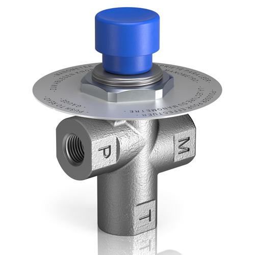
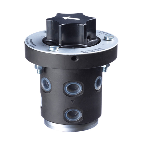
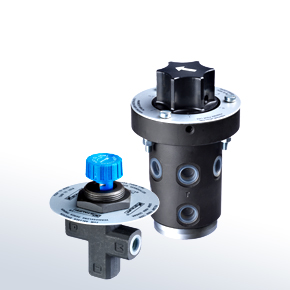
In normal condition fluid is completely isolated from the gauge until the knob is pressed. By pressing the knob fluid is connected directly from pressure port P to gauge port G giving instant and accurate reading on the gauge or the manometer. As the knob is released the spring loaded spool closes the pressure port automatically connecting the gauge port G to drain port T. In operation an orifice (0.8mm dia.) in Gauge Port acts as partial snubber, protecting the gauge from damaging pressure surge of fluid as the knob is pressed.

CONTACT US

  • House No. 434/4 Near Shishu Wala Talab Village Mundka, Near Mundka Metro Station Gate No.-2, Delhi-110041, India
  • +91-9899300154
  • +91-9899300254
  • sales@nrts.in
Contact Now